Thursday 22 January 2015

How I Made A Cat Wheel 4

http://cache.boston.com/bonzai-fba/AP_Photo/2006/05/21/1148184569_5086.jpg
Its on the brain

ALL TOGETHER NOW

Im writing these blog entries in the order that I constructed my cat wheel which means some steps done for aesthetic purposes occurred before some of the more important functional steps. However, that's the way it goes sometimes. 


THE COVERING 1

Around the outside of the wheel I wanted to have something that would cover the beams under the track. For this I used 810mm x 1200mm 3mm MDF cut to slightly larger dimensions than the plywood track (417mm x 1200mm). The extra length was due to MDF not having any grain to use in assisting the bend so I used the longer lengths resulting in fewer individual pieces needed. The extra width was so it could cover the beams and extend over the 12mm thick plywood circle. I screwed the MDF into 12mm plywood circle on the back edge of the wheel and into each beam along the front. Again, I took into consideration the longer timber screws that will be going into the beam and left a couple of centimetres from the edge when screwing down the MDF.


Unfortunately the cut pieces didn't make an even fit around the wheel leaving about a 10cm gap between the first and last piece. At the time of writing this post I haven't fixed it yet, but I assume I will just cut a small piece to fill the gap. However, the problem here is how to have them run smooth against each other because, unlike the track, I'm not wanting to overlap any pieces. The other issue this has caused is the MDF boards not joining at a beam, and even if they did I wouldn't want to drill both boards into the one beam. This resulted in the edges of the MDF sticking up. I fixed this by attaching a little latch that could be screwed into each MDF holding them tight enough together to lie flat. Apparently MDF doesn't hold a screw well on its own because there is not wood grain to hold the screw thread, so I bought some screws with back nuts so the MDF wouldn't be holding the screw like the beams and the plywood are holding the other screws. The oddness of this will end up being covered up by the front panels.


THE CASTOR

The Castor/spinning mechanism ended up being a bit tricky, and was the main thing I was referencing in the intro of the previous post. In the end the solution to the problem was very simple. Ill explain later. 

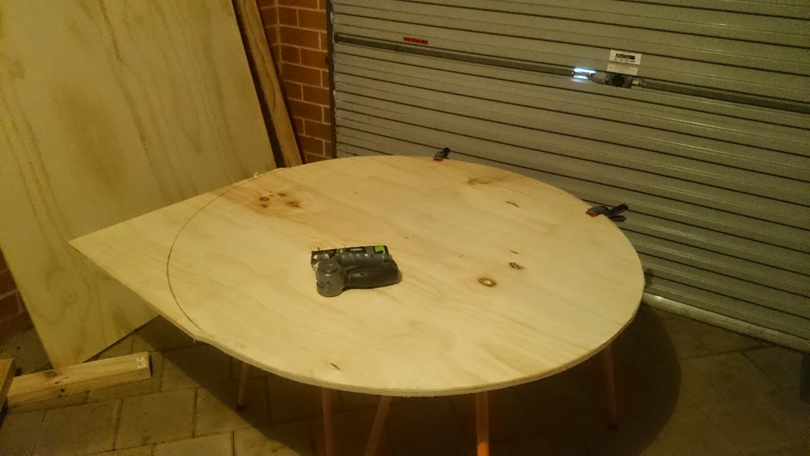
The positioning of the castor directly in the middle of the plywood circle was done by using the hole from the nail that was used to draw the original circle outline. I positioned the castor then drilled into the four bolt holes of the castor through the plywood circle. The bolts that came with the castor were longer than I wanted, so if I had used them it would have meant the long screw end of the bolt protruding in the middle of the cat wheel because doing it the other way would have meant the bolt length would have prevented the castor from rotating. So I bought shorter bolts so I could have the nicer presentation of the bolt head in the middle of the wheel while the screw end didn't interfere with the rotation. 

Before attaching the castor to the wheel I positioned the castor on the upright of the frame, and drilled it into position about 600mm up the frame. Based off the circle's radius of 582.5mm plus the uprights 45mm height off the floor that the legs provide, a height of 600mm for the castor will give the wheel plenty of clearance off the floor but not too high so the cats wont be able to reach it.

From here it was "simply" attaching the two pieces together and locking it in place.


The issue I mentioned before was that when I first attached the wheel, castor and frame together, as seen in the pic above, the wheel was on a slight angle towards the rear at the bottom and would hit the support beams of the frame as it spun. I wasn't sure why this was happening and initially I thought it was because the castor couldn't sit flush against the upright due to it being rounded on one side creating an angled lean of the wheel. So, rather than think about it any harder, I went down to the shop and bought a couple of different casters to try that would sit flush. This resulted in proving one thing for sure .... I need to think harder. The angle of the wheel became worse and it was now rubbing so hard it couldn't spin smoothly. The plus side was that the new castors illustrated the problem much clearer. The weight of the wheel was causing the rotating part of the castor to bend downwards. My original castor was the most heavy duty and bent the least, so I went back to using the original castor but I added a piece of the 42mm x 19mm timber to the upright in order to give the wheel more clearance between it and the frame.

The Joy Of Drilling, or 
Trial and Error: The story of a guy who measured once and cut many many times

Next: the finishing touches, an uninterested cat and the next project: cat adoption.

Tuesday 20 January 2015

How I Made A Cat Wheel 3

 
 Patience my furry little friend.
CAT WHEEL-ISH

The next couple of steps resulted in some trial and error experiments on my behalf, which I wont bore you with at this stage, but as a result there are a few extra drilled holes and some misaligned wood pieces here and there. Nothing major in terms of function or aesthetic, it's all part of the learning curve.

THE FRAME, part 2

In order to give the upright beam of the frame greater stability I added support beams to either side. When I bought my cheap hand saw it came with a cut guide which had the 45 degree angle that I needed to make the beams fit. I dont know how much support the frame actually needs but I decided that having it connect with the upright higher and the bottom base wider would make the most sense in terms of dispersing weight and movement. But I might be wrong. I measured the wood, starting from where it would be at the widest it could go on base (just on the inside of the screws that connect the base to the legs) and then the 45 degree angle cuts determined how far up the frame they would go.


Once again the good ole timber screws were used to connect the supports at the top and bottom. Im not aware of the best technique for connecting screws at the angle, so my approach was more "ram it in until it goes in right" rather than a specific technique. The main thing I tried to keep an eye on was that the screws that connect to the upright would not run into the ones from the other side of the upright, hence the ones in the picture being a little off center.


THE TRACK, part 2

The next step for the track was to attach the 3mm plywood onto the 305mm long beams. This is to create the track surface that the cats will (hopefully) be running on. I originally wanted to use as few individual pieces of plywood for the track surface as possible, meaning I would cut the 810x1200 plywood lengthwise resulting in 3 pieces of 305x1200 to complete the track. However, the plywood I bought had the grain of the wood running down the length and I decided in the end that it would be best to use the flexibility of the grain to assist with the curve of the track rather than bend the wood against the grain and risk breakage (highly unlikely with 3mm ply but lets keep it simple, stupid). So, the 2 sheets of 810x1200 3mm plywood created the 4 pieces of 810x305 3mm plywood needed for the track surface. 

The task now was to clamp and drill the 3mm plywood track sheets onto the 18 beams. I clamped all the pieces into place so I could get the positioning close enough before finalising their placement with drilling. The drilling was easy enough, but I made sure to gently press on the back of the beams so that there was counter pressure on the opposite side I was drilling into as I wasnt too sure of the stability of the individual beams to take the pressure of the drilling. Due to working about 8-10mm in from the circumference of the circle there was enough overlap of the sheets to allow the joins to occur at a beam so the screw would go through two sheets and into the beam where the separate sheets meet. The plan it to put a yoga mat over the track surface so the cats have something more comfortable to run on, which I am hoping to smooth out the join. 


I drilled through the plywood into each beam at the base and near the end of the beam to hold down the track. I made sure that I gave sufficient room at each end so these smaller screws don't run into the larger timber screws holding the beams to the circle and the screws that will eventually be inserted into the exposed end of the beams for the cover (more on that later). Then, after 18 beams, four plywood sheets and some choice curse words when the screws wanted to abide by gravity rather than doing what I wanted them to do, I ended up with something that doesn't look unlike a cat wheel.


 Excitement building.

Friday 9 January 2015

How I Made A Cat Wheel 2

Getting Closer

TAKING FORM
Today I began construction of the cat wheel frame that will hold up the wheel and be attached via the rotating mechanism/castor, and I also cut and attached the beams for the track. 
THE FRAME, part 1
I used 3 of the 90mm x 45mm for the frame base. These were cut into 2 pieces 600mm in length and one 900mm in length. These lengths were based on guestimates of other peoples' designs where the width of the frame was about 2/3 the diameter of the wheel and the depth of the frame had legs stuck out further in the front and in the back than the depth of the wheel. I assume these dimensions would be for stability and minimise any rocking, but then again they may just be an aesthetic choice of others. However, the fact that it pops up fairly consistently across designs makes me think its the former. 

I decided to attach the 900mm plank across the top of the two 600mm legs (rather than flat along the ground) so that there would be least amount of wood on the floor as we have wood and tiled flooring (which may not be necessary as Im thinking of attaching small non-slip mats on the feet), and because I think it looks nicer. 

As you can see in the picture I attached the planks using three timber screw on each end. Prior to inserting the screws I drilled pilot holes in both planks using a drill bit about 3/4 the size of the screw. This is to prevent wood from splitting, or so Im told. I also used liquid nails between the join to give me greater strength and stability.


I then attaches the 1200mm plank for the up-right part of the frame. I positioned this perpendicular to the bottom plank because the bracket on the caster fits near perfectly around the thickness of the plank. I used the same method attaching the up-right that I use for the feet; pilot holes in both pieces then three timber screws and some liquid nails.

From here I plan to attach a support frame to either side of the upright, attach the caster, then it should be ready to go (any aesthetic modifications aside).


THE TRACK, part 1
 
After I cut the large circle I got to measuring the 1.2m long 42mm x 19mm planks into 305mm lengths. 305mm being the width of the track that I am wanting. Most other people around the web have gone for 12inch tracks (304.5mm) so, while it does look like it might be a little narrow for my cat I was finally persuaded when 305 divided neatly into 1220 which means 4 even pieces of track from the 3mm plywood. Best to keep it simple, stupid. 

One of my 42x19 had a few knots outs of it and a couple of cracks so I left it out of the running for being part of the track and cut 5 of the planks into three 305mm beams. This was how I came up with the magic number of 18 beams. Mmmmm, Scientific. 

Again I drilled a pilot hole into each end of the 18 beams, and drilled 18 pilot holes into the 12mm plywood circle 203mm apart and about 8mm in from the edge of the circle. This was so the beams would be evenly spaced around the circle and would run flush against the cut edge of the circle once attached. 


I then pierced the circle pilot hole with the timber screw so that the tip had come out the opposite side before dabbing a small amount of liquid nails on the end of the beam and positioning it on the exposed tip of the screw. Then it was drill, then pierce, dab, drill, pierce, dab, drill, repeat. I was also wiping away any excess glue that oozed out the sides after each beam.

Its starting to not just look like random wood.

Next Ill be either doing the supports for the frame or trying to attach the running track without breaking the wood, or my spirits. 

Do cats feel gratitude?

Thursday 8 January 2015

How I Made A Cat Wheel 1

Hopefully Not Like This

THE BEGINNING
I've decided to attempt to build a cat wheel. I have never attempted anything like this before so I am hoping there will be minimal mistakes, complications and injuries.

I have no experience working with wood, so this may be quite the catastrophe in the making. If anyone ends up reading this that knows more than nothing please feel free to offer suggestions and corrections in the comment section.

I have searched online for instructions and guides for how to do this, but there hasn't been much to go by. I found a few other people who have successfully attempted this before who I have generally followed and received inspiration from for my construction. Primarily I have used Crystal W's video (http://youtu.be/LEdnCGfoHkM) as my main guide.
I also looked over Stitches & Sew's blog (http://stitchesnsews.blogspot.com.au/2013/02/home-made-cat-wheel.html) and Nicheven's video (https://www.youtube.com/watch?v=m5Y3lNRp8cs). Various bits and pieces were taken from each source.

Nicheven emphasised their disclaimer for non-liability, etc. So, while I dont think it is necessary, I might as well play it safe and claim that this blog is not a recommendation for how others should assemble a cat wheel, but if any individual chooses to do so then any consequences that come about as a result of their attempts are the sole responsibility of the individual, not the writer, me...dont sue me....Im talking to you, Americans....and other nations too.

Most other sources use imperial measurements when describing their construction, but as Im in Australia Ill be using metric. Also, nearly all of my materials were purchased from Bunnings, so while there may be different products or dimensions that are preferred I pretty much stuck to what was easily available at my local Bunnings. 

MATERIALS

At the time of writing this post I have only just started and I am expecting to make a few more runs to the shop before Im done. I may update this original post as I go with all the materials Ive used, or I may just mention it as I go in subsequent posts. But for now I have started with the following materials:

1x 12mm,  1198mm x1200mm, sheets of plywood
      this is for the main backboard of the wheel. It came pre-cut at my local store, most other places sell it as 1200x2400 sheets. I assume the saw used loses 4mm.
3x 3mm, 810mm x 1200mm sheets of plywood.
     these will make up the inside track. At the time of writing this post I havent decided what I will use for the outside of the wheel so I may need more of the same, or else I will get something of a bit nicer quality.
6 or so 42mm x 19mm x 1.2m pieces of timber.
     these are for the beams for the track to attach to.
3x 90mm x 45mm x 1.2m
     these are for the frame. (I will definately need more for the frame.)
1x castor
   for the rotating mechanism.


THE WHEEL

I decided to go with a wheel 3660mm in circumference/1165mm in diameter. This size was chosen with the hope that it would make the construction of the track easier due to the length of the 3mm ply dividing evenly into the wheel circumference and hopefully making it easier for myself and smoother for the cats. However, I think I will be using the width of the 3 mm ply and cutting along the length due to the grain of the wood naturally bending in this direction which I assume will make the track placement easier. We'll see.

I measured out the circle using a string the length of the desired radius (582.5mm) tied to a nail in the centre of the 12mm ply and a pencil at the other end of the string. To cut the circle I used a cheap Otizo jigsaw that I managed to pick up. Im using the cheap version of most things that are needed due to this being my first attempt at woodwork and if it doesnt work out I may never do it again. The cut quality is definitely good enough for me, no issue there, but I imagine other saws would have a lot more power behind them, and the battery life is fairly poor. Fortunately it comes with a spare battery that can be on the charge while I use the other one.

I bought a set of extra blades for the saw so I could have a selection for various purposes. The one I used for the circle was the one recommended for fine cuts and curves. No need to doubt the packaging.


Next I'll be starting the frame and/or starting the track, depending where the mood takes me.